Physical Installation
Warning
Installation should only be carried out by trained installation personnel. Plumbing and electrical work should only be carried out by qualified plumbers and electricians respectively.
Requirements
To install a FlowStop, the following parts are required:
- FlowStop control unit and valve unit
- Double gang pattress back box, min. 45mm depth
- Mains switched fused spur with 3A fuse
The following parts are not included but are recommended where appropriate:
- 2pcs WRAS approved ¾” tap connector
- Pressure reducing valve
- Inline water filter
The valve unit should be installed in an accessible location for ease of maintenance.
The FlowStop valve unit has only been tested and certified for use with cold drinking water. If used with hot water, ensure temperature does not exceed 60C.
The control unit must be installed in a location that is accessible to the end user.
Plumbing the Valve Unit
Warning
The valve unit must be installed by a qualified plumber

Read all the instructions before starting.
The valve unit should be installed on the mains incoming cold water supply, immediately after the water stopcock and any required pressure reduction valves.
The valve unit is a sealed unit and contains no user serviceable parts. Do not disassemble as this may damage the internals and will void the warranty.
The valve unit has ¾” male BSPP threads and requires WRAS approved fittings (not supplied). A tap connector should be used to facilitate easy installation and removal.
If required, an additional valve unit can be connected to the control unit.

Procedure:
- | Isolate the mains water supply and drain the system as necessary.
- | After the mains stopcock, cut and remove enough copper pipe to accommodate the valve unit. If a pressure reducing valve and/or filter is used, install the FlowStop after this.
- | Fit the valve unit using suitable ¾” WRAS approved fittings, taking care to observe the water flow direction marked on the enclosure. Ensure that the fiber washer is not missing from the fitting. Take care not to overtighten the fittings as this may damage the valve unit – maximum 25Nm torque.
- | It is recommended to install an isolation valve after the valve unit for ease of maintenance.
- | Turn on the mains stopcock and check for any leaks.
Check with an electrician whether any copper pipework is used for earthing – as the valve unit is plastic it may need an earth bonding bridge to be installed.
Warning
The water pressure through the valve unit must not exceed 10 bar. If greater than 10 bar, a suitable pressure reducing valve must be installed.
Important Note - Pipework Chlorination and Purging
Flush all pipework before connecting the FlowStop valve unit to ensure installation debris (e.g. solder) cannot get stuck in the valve.
Ensure that all FlowStop valves connected to the water system are OPEN before flushing the system.
Ensure that all pipes are thoroughly flushed through with clean drinking water after chlorination.
Extended exposure to chlorinated cleaning solutions may cause damage to the valve seals, compromising the protection of the system. Do not allow any valves to close until after every pipe has been flushed with clean water.
Mounting the Control Unit
The FlowStop control unit is designed to be installed in a standard British double gang dry lining or surface pattress box. This needs to have a depth of at least 45mm.
Mount the control unit in an easily accessible position so the resident or end user can quickly identify leak alarms and restore their water supply after an alarm.
Connecting the Mains Power Supply
Danger
Follow safe isolation procedures and do not work on the device while it is connected to live mains electricity.
The control unit mains supply is connected using the large 5.0mm 2-way pluggable connector at the top right of the PCB. Refer to the wiring diagram below.
Mains power should be provided by a fused spur with a 3A fuse installed by a qualified electrician.
Mains power must be connected using 2-core or 3-core flexible stranded cable rated for at least 3A at 240V (0.5mm2 to 1.5mm2). If a metal back box is used, 3-core cable must be used with the earth bonded to the back box.
Live and Neutral are interchangeable, although we recommend following the labels on the PCB for safety and ease of maintenance.
| Terminal | Wire Colour | Description | Notes |
|---|---|---|---|
| L | Brown | Live | 100-240VAC 50/60Hz |
| N | Blue | Neutral | 250mA PTC Fused |
Control Unit Wiring
The FlowStop control unit comes with pluggable connectors. The screw terminals on the pluggable connectors are rated for between 1.3mm2 and 0.13mm2 (16 AWG to 26 AWG) conductors. We recommend 0.75mm2 YY control cable. Exceeding this range may cause poor connection or damage the terminals.
All wires should be terminated with ferrules to ensure good electrical connection.
Wiring Diagram

Connection Table
| Section | Terminal | Wire Colour | Description | Notes |
|---|---|---|---|---|
| VALVE 1 | V+ | Red | Positive valve control | For use with Andel approved valves only |
| V- | Black | Negative valve control | ||
| SIG | Blue | Flow sensor signal input | For use with Andel approved flow sensors only | |
| GND | Yellow | Flow sensor ground | ||
| +5V | Green | Flow sensor power | ||
| VALVE 2 | V+ | Red | Positive valve control | For use with Andel approved valves only |
| V- | Black | Negative valve control | ||
| SIG | Blue | Flow sensor signal input | For use with Andel approved flow sensors only | |
| GND | Yellow | Flow sensor ground | ||
| +5V | Green | Flow sensor power | ||
| LEAK | LEAK - | Blue | Leak sense return | For use with Andel leak sensors only |
| LEAK + | Red | Leak sense power | ||
| RELAY 1 | NO | Normally open | Volt-free contact - max 30V 1A | |
| COM | Common | |||
| NC | Normally closed | |||
| RELAY 2 | NO | Normally open | Volt-free contact - max 30V 1A | |
| COM | Common | |||
| NC | Normally closed | |||
| 12V OUT | +12V | 12V power | Unprotected auxiliary power; max. 125mA | |
| GND | Ground | |||
| MODBUS | GND | Do not use | Not implemented | |
| B | ||||
| A |
Incorrect use of terminals may cause damage to the FlowStop control unit or may cause unpredictable behaviour.
The 12V output is intended for use with the built-in volt free contact relays to control external beacons or power relays. This output is only suitable for a maximum power draw of 125mA (1.5W) – exceeding this limit may cause the unit to fail unpredictably.
Valve Unit Wiring
The FlowStop valve unit comes pre-terminated with 2m of lead. If a greater distance is required between the control unit and the valve unit, this can be extended with DEF-STAN 16-2-6A unscreened 6-core 0.5mm2 cable or equivalent.
Control of the valve is pulse-on pulse-off and holds its last position whether power is connected or not. Do not connect the valve V+ and V- directly to a power source as damage may occur. The FlowStop valve unit should only be used with the FlowStop control unit, except under instruction from Andel technical support.
Valve 2 is disabled by default, and can be enabled using the valve menu.
Connection Table
| Terminal | Wire Colour | Description |
|---|---|---|
| V+ | Red | Positive valve control |
| V- | Black | Negative valve control |
| SIG | Blue | Flow sensor signal input |
| GND | Yellow | Flow sensor ground |
| +5V | Green | Flow sensor power |
| N/A | White | Not used |
Output Relays
The FlowStop control unit features two independently configurable SPDT relays, which function as volt-free contacts for onwards communication and controlling external devices.
Each relay is rated for 1A 30V. These relays are not suitable for directly driving motors or solenoids. In such cases, the Andel Auxiliary Output Relay Panel or Solenoid Valve Control Panel or must be used.
For configuration options and default settings, see the Setup section.
Note that in power loss detection mode, the relay is held open (COM connected to NO) under normal conditions and will switch closed when mains power is lost.
Optional Leak Detection Sensor
If required, an optional Floodline® water leak detection sensor can be added to the system to provide additional leak detection coverage in risk areas of a property. Options include the Flexi-Pad, 1- Zone Cable, or Point Sensor. Multiple sensors can be chained together, but the control unit will treat them as a single combined leak detection zone.
Connection to a specific sensor will be detailed in the manual for that sensor and the connection to the FlowStop® control unit. Ensure that only one EOL resistor is used.
The volt-free outputs from other Andel Floodline® leak detection panels can also be used to trigger an alarm on FlowStop – contact sales for more information.
Initial Power-Up
On first start-up, the following steps must be followed to check that the system is installed correctly and will work as expected.
This procedure requires you to have mains water and electricity available.
- Before applying power, close the main water stopcock.
- When power is first applied, the screen and all three LEDs should light up. The screen should display the Andel logo.
- Any attached valve units will briefly close then open, the yellow service LED and red alert LED will go out. The green power LED will remain lit.
- The main screen should then load, showing the green status bar at the top with “System OK” displayed.
- The measured flow rate shown in the middle of the screen should show “00.0”
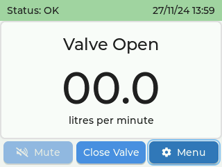
- Now open the main water stopcock. You may see the flow rate increase briefly as the water flows through the valve unit and fills the pipes. If no water is being used downstream from the valve unit, flow rate should then settle back to 00.0.
- Open a tap to check that water flows as expected and that the flow rate number displayed on the control unit is as expected.
- Leaving the tap running, on the control unit use the arrow keys to navigate to and click enter on the middle “close valve” button. You may hear a noise from the valve as it switches closed.
- Check that the water flow has stopped at the tap. Close the tap again, and use the “open valve” button to restore water flow.
Please refer to the Setup and Provisioning section for further steps in configuring the FlowStop 2 unit.
Maintenance
The FlowStop control unit and valve unit contain no user serviceable parts. Any attempt to disassemble either the control unit or valve unit will void the warranty.
We recommend testing your FlowStop on a regular basis to ensure it is working properly.
From the main screen, with no alarms active, the “close valves” button can be used to manually toggle the valve closed and open. Check that the valve completely stops the flow of water when closed and allows free flow when open.
In addition to regular testing, we recommend yearly maintenance by an Andel approved engineer.